Download the SVG Toolbar Icon
Can be installed via the AddonManager in Tools menu -> AddonManager. After restarting the AddonManager you should find MeshRemodel in the list of workbenches you can install.
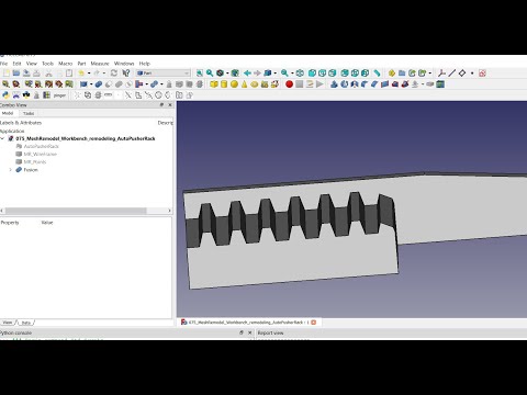
Use this workbench to aid in remodeling imported mesh objects. The preferred workflow is to select the mesh, then click either create points object or create wireframe object. This creates an object with selectable points or edges at all of the mesh vertices or edges. Use the selectable points or edges to create Mesh Remodel elements, such as points, line segments, arcs, circles, or bsplines. You can then select those created elements and form a wire using the create a wire (Draft upgrade) tool, which wire can then be also upgraded to a face. The face can be used with Part Extrude, Part Sweep, Part Revolve, and Part Loft tools to create solids.
Select the mesh object in the tree, then use this command to create a points object containing all the vertices of the selected mesh object. The points object is a compound consisting of Part Point (vertex) objects, one per vertex in the selected mesh. The purpose of this object is to provide selectable points in the 3d view. We can use these selectable points with the other tools in the workbench to create the lines, circles, arcs, and polygons needed to remodel the mesh.
If you hold Ctrl key down while invoking this command the mesh object will be made partially transparent and non-selectable in the 3d view. You can still select it in the tree view, but it will not appear to be selected in the 3d view and on mouse over you will not see it change to pre-select color. This will make it easier to see the MR_Points object. These settings can be changed in the mesh object's view tab in the property view.
Update: As of v1.82 you can now also create a points object from a Points cloud object created in Points workbench, which are non-selectable. So, if you need to be able to select the individual points in a points cloud use this tool to create the selected points object. Because the Points cloud object points are non-selectable the algorithm uses the first 3 points in the object to define the plane. If those 3 points are colinear then it won't work.
Select the mesh object in the tree, then use this command to create a wireframe object containing all the edges of the selected mesh object. The wireframe object is a compound consisting of Part Line objects, one per edge in the selected mesh. The purpose of this object is to provide selectable edges in the 3d view. We can use these selectable points with the other tools in the workbench to create the lines and polygons needed to remodel the mesh.
If you hold Ctrl key down while invoking this command the mesh object will be made partially transparent and non-selectable in the 3d view. You can still select it in the tree view, but it will not appear to be selected in the 3d view and on mouse over you will not see it change to pre-select color. This will make it easier to see the MR_WireFrame object. These settings can be changed in the mesh object's view tab in the property view.
Convenience link to 4 commonly used tools to create Solids in Part Workbench. Links to the Sweep, Loft, Revolve, and Extrude commands. Some preprocessing is done in order to sometimes enable solid creation while bypassing the Gui dialogs. For example, you can select the Sweep profile in the tree view and the edge to sweep the profile along in the 3D view to create the Sweep without ever opening the Sweep dialog. If you don't get the selections right then the dialog will appear as it normally does in Part Workbench.
Usage: Select your profile object in either the tree view or the 3D view, then optionally select and edge to be used as a direction, and then click the toolbar Part Solid icon. If the profile is closed and planar we set Solid = True, else Solid is set to False. Be sure to check the Solid property of the created Extrude object. If it's not set to Solid = True, then chances are the wire used wasn't closed or wasn't planar. If an edge is selected it is linked to the Extrude object and becomes a dependency. The LengthFwd property is set to the length of the selected edge. If no edge is selected 10 mm is the LengthFwd and the direction mode is set to "Normal". If the normal can't be determined the direction mode is set to "Custom", which defaults to Z = 1 direction. If the Extrude is done in the wrong direction, just toggle Reversed to True in the Extrude property view.
Usage: Select your profile in the tree view and your edges to use as the path for the sweep in the 3D view, and then Ctrl + CLick on the toolbar icon. More than one profile (section) may be used with Part Sweep. It is important to select them all in the tree view because that's how we determine which selections are the profiles and which are the paths. All path edges must belong to the same parent object. This is a requirement of the Part Sweep tool and there's nothing to be done about that except to put all the edges into the same object. We can do that in a number of ways. The preferred way is to create a wire from those edges and use the edges of the wire for the path. Another method is to create a SubShapeBinder object from those edges. MeshRemodel will create a SubShapeBinder for you if you choose that option in a popup dialog. You will have 2 options for the Binder: parametric and non-parametric. If you choose parametric the Binder and the Sweep will adjust themselves automatically to changes in the edges to which the Binder is linked. The downside to this option is now you cannot delete those objects without breaking the Binder and the Sweep. (You can set the Binder's BindMode property to either Detached or Synchronized to change this, but once detached the links are gone forever.) After creating the Binder you will then need to try again, this time selecting the edges of the Binder instead of the original edges, which will now be hidden to prevent accidental selection.
RECAP: Select the profile first in the Tree view, and then the path edges in the 3D view.
Usage: Select your profiles in the tree view or in the 3D view and Shift + Click the toolbar icon to do the Loft. A limitation of the Part Loft tool is the profiles may not contain inner wires (for example, donut shape). The Gui dialog checks for this and you don't even see the profiles with inner wires in the selection column as options, but no checks are done here. This same limitation applies to Part Sweep, but not to Part Extrude and Part Revolve. (But Part Extrude cannot extrude such profiles at a taper.)
Usage: Select your profile in the tree view or the 3D view and optionally your edge to serve as an axis of revolution, and Alt + Click the toolbar icon.
Select the mesh object in the tree, then use this command to create one or more cross-section objects. This is just a convenience link to the Cross-sections tool in the Mesh Design workbench. These cross-sections should not be directly used as wires, but rather as references for creating the wires within the MeshRemodel workbench. This is because these cross-section objects will have extra points and multiple line segments where only one segment is desired.
Select 3 (non-colinear) points from the points object in the 3d view to enable this command. It creates a new points object filtered to contain only those points that are coplanar with the 3 selected points. You can recreate the profile inside the sketch using those external links and the sketcher tools or directly in the 3d view using the MeshRemodel tools. The Coplanar Points Object (CPO) is now a feature python object.
In order to filter the original points object into a set of coplanar points aligned on the plane defined by the 3 selected points an internal isCoplanar algorithm is used. There is a settings option for changing the tolerance level. The smaller the number the fewer points get produced. The filtering is done by using the 3 selected points and each other point in turn to create a tetrahedron. If the 4 points are coplanar, then the tetrahedron should have volume ~= zero. Default tolerance is 0.01 mm^3. If too high a tolerance value is used you will get points that are not truly coplanar, but they will forced into coplanarity by projecting them onto the plane.
This is typically a MR_Points object. It is the object upon which the CPO is based, so do not delete it or else you will break the CPO.
Trigger. Triggers a command and sets itself back to False. Explodes the CPO just as if you had used Part workbench Compound Explode tool on it. The points are now individually editable, meaning you can delete the ones you do not want or adjust their placement properties. This also makes them selectable via the Shift+B box selection tool. Adjusting placement of individual points can be very handy at times, so remember this feature, but be wary of the working plane when moving points.
Trigger. Triggers a command and sets itself back to False. Makes a new sketch, attaches it to the Trio points (the 3 points of the BasePoints object originally selected when the CPO was first created) using MapMode = "ThreePointsPlane", and adds all points in the CPO to the sketch as links to external geometry.
Adjust this to change the point size for this CPO (does not change default value in the settings). The same property is available in the view tab, but this overrides that one. It is here for convenience.
These are the vectors of the points in the CPO. They are not readonly, but you should not modify them directly because they get recreated with each recompute. I was intending to make this property readonly, but in that mode you cannot access the editor and see the table view. If you want to remove or modify individual points, use the Explode Compound feature.
Tolerance defines how the points that are coplanar are selected. I will likely be changing the algorithm in the future, but for now a 4 sided tetrahedron is created with vertices: the Trio and each other point in the BasePoints object in turn. If the volume of the tetrahedron is tolerance or less the 4th point is considered to be on the plane. Higher tolerance values will produce more points in the plane. Do not worry about the extra points not being on the plane as they are projected to the plane. Setting Tolerance = 0 means do not use any tolerance, but rather put all the BasePoints object points in.
These are the 3 vertices you selected when you first created the CPO. They are used in a number of ways. If a sketch is created they are the support for the sketch attachment. When the CPO is created they are used to define the plane.
This enables preselection mode where points get automatically selected by holding Ctrl key down while hovering over the point in the 3d view. This is intended to make it easier to select all the points needed for making bsplines since there are usually very many points needing selection, but will work with all MeshRemodel tools that create objects from selected points. DO NOT mix selection modes in the same operation. For example, if you select any of the points using Ctrl+preselect mode, then do not click on any points to select them in the usual way for the same operation or else it is likely to fail.
Click the icon to enable or to disable Auto Preselection Mode. There is also a button that will appear in the status bar when this mode is active to indicate you are in Auto Preselection Mode. You can also click that button to remove the selection observer and return to normal selection mode.
The way the selection observer works is it monitors the preselection of points (only Vertex type objects). If you are holding down the Ctrl key when the point is first preselected (hovered over with the mouse) that point gets added to a list variable internally called global_picked. When you use one of the object creation tools that uses selected points, e.g. the bspline or line tool, the tool code will check to see if global_picked contains points, and if so, will use those points. These global_picked points are not updated if a point is normally selected (by clicking on it). (But if you deselect a point by clicking on it, then the point will be removed from the global_picked list.)
Select a vertex (or any arbitrary point along any edge or face as of version 1.61) in the 3d view, then use this command to create a point object at that location. The point object is a Part::Vertex that we can use in some operations, such as Part::Loft or in subsequent Mesh Remodel operations, such as creating a line segment or arc. You must select some object first. A point cannot be created in any arbitrary empty location, but you can create a point on an edge, for example, and then move it to the desired location.
Select 2 points or 1 edge in the 3d view to enable this command. It creates a Part Line object using the 2 selected points or the selected edge as a reference. Note: any 2 selectable points may be used, even points that are part of an edge (the edge is shown selected in the 3d view, but the point at the mouse position is the one used), sketch, 3d object vertex, circle, etc. If you can see it in the 3d view and select it, then it most likely can be used with this function. If you select an edge the first point and the last point of the edge are the points used, so curved edges will likely produce unexpected results.
Use Ctrl+Click to include a point at the midpoint of the line. Use Ctrl+Shift+Click if only the midpoint is desired.
In the report view you will find some basic information about the line, including its length and coordinates of its midpoint.
You may elect to remodel the object inside the sketcher using the sketcher line tools instead of this, but it is here for those who wish to use it instead. The reason it was previously recommended to use the sketcher is some of the polygons created with this tool might not be coplanar, and might give problems with future operations. But I have found that when you have a coplanar issue you can usually (usually) click upgrade (Create a wire tool) twice (first to make a wire, second to create a face), then use the face successfully where the wire might have failed.
Select 3 or more points or 2 or more edges in the 3d view to enable this command. It creates a polygon from the selected points or edges. You should not mix points and edges in the same polygon. Choose either one object type or the other, but not both. Note: this is not a regular polygon, meaning the side lengths are not necessarily all equal to each other. The order of selection is important. By default the polygon will be closed, but you can prevent this with Shift+Click when selecting points. When selecting edges the polygon will only be closed if the last edge connects back to the first edge.
When selecting using Shift+B, block selection, the points will generally need to be sorted or else you will get a polygon which zig zags all about. To enable sorting using Alt+Click. The sorting algorithm takes the first selected point, then finds the nearest point among the other selected points, and puts it 2nd. Then it uses the 2nd point to find the next nearest point, and puts it 3rd, and so on.
The polygon object created is made up of individual Part Lines. This will enable you to delete any lines you would prefer not to have, for example if you get a closed polygon, but would prefer it not to be closed or if some lines get crossed, etc. Use the Create wire tool to upgrade the individual lines to a single wire object, and then click it again to create a face from the wire. My experience is faces created in this manner are much less likely to fail in a future sweep or extrude due to being non-coplanar.
Select 3 or more points in the 3d view to enable this command. It creates a BSpline from the selected points. The order of selection is important. By default the BSpline will be closed, but you can prevent this with Shift+Click. The points need not all lie on the same plane, but if they are not all on the same plane you will not be able to create a sketch from this later. Sometimes points that appear to lie on the same plane are not actually on the same plane. It is better to create the bspline in the sketcher.
This command supports block selections (Shift+B, draw rectangle). Generally, the points will need to be sorted when using that block selection method. Use Alt+Click to sort. See the section on Create polygon for details on the sorting algorithm used.
Select 3 (or more) points in the 3d view to enable this command. It creates a circle from those first 3 selected points. Any points after the first 3 are ignored, but you are allowed to select more. This is to support easier block selection mode (Shift+B, draw rectangle). Use Ctrl+Click to add a point at the center of the new circle. Use Ctrl+Shift+Click if only the center is desired.
In the report view you will find some basic information about the circle, including its radius and coordinates of the center.
Select 3 points in the 3d view to enable this command. It creates a Part Arc (internally using Part.ArcOfCircle() function) from those 3 selected points. Use Ctrl+Click to include a point at the center of the arc. Use Ctrl+Shift+Click if only the center is desired.
In the report view you will find some basic information about the arc, including its radius and coordinates of its center.
Select 2 or more objects to enable this command. It uses Draft.upgrade() to connect the objects into a single wire. It is here as a convenience. Note: the selected objects should all be connected together, but need not necessarily form a closed loop. For example, you might have an arc and 2 lines connected one to each end of the arc. You should not include circles unless you wish to connect them to other objects (not common). The idea here to create wires from connected lines, open polygons, and arcs, then use these new wires, along with existing (coplanar) circles and closed polygons to create a sketch with the Create Sketch tool or you can also use the wires directly with Part workbench tools like, extrude or sweep. As noted in other sections of this document, it is often useful to use this again on the created wire to form it into a face. Faces tend to work better with other tools rather than wires, particularly in cases where the tool complains the wire is not coplanar. If you get that error message run this tool again on the wire and upgrade it to a face. Then try the tool that complained the wire was not coplanar again.
Creates a sketch, optionally attached to 3 points on a plane if 3 points are selected. This does not create any links to external geometry. See Create coplanar points command if you want to automatically import all coplanar points that lie on this same plane.
Use Ctrl+Click to make a sketch out of selected circles, polygons, etc. If a circle or arc is the first selected object, it will map the sketch concentrically to that circle or arc. Note: there is a known issue using this method that sometimes objects that appear to be coplanar might not actually be coplanar. It is recommended to remodel using the sketcher with links to external geometry to the points objects instead of this method. Uses method of creating a single sketch from all selected objects.
Use Alt+Click to create multiple sketches, one from each object selected, and then merge them all together into a single sketch, deleting the temporary sketches afterward. This can sometimes resolve coplanar issues.
Use Shift+Click to create a sketch based on picked points. A new picked points object is created containing all the picked points. The first 3 selected points will define the plane to map the sketch to. All the picked points get added to the sketch as links to external geometry.
Select 2 or more sketches to enable this command. This uses Sketcher workbench merge sketches command. It is here as a convenience.
Opens Sketch workbench validate sketch tool. Enabled only if you have 1 sketch selected. It is here as a convenience. Occasionally, sketches will have missing coincidence constraints. That tool is good for fixing that issue. It can also be used to easily remove all links to external geometry.
This setting will keep the toolbar active after leaving the workbench, but you have to open the workbench at least once each session. After that, if this is enabled, when you leave the workbench the toolbar will appear in the new workbench after a couple seconds. This can be a great time saver as you would often use this tool in conjunction with Part workbench in remodeling a mesh. This would prevent the need to switch back and forth between workbenches.
This sets the point size on all points created with the workbench. It does not affect objects already created after the setting is changed, only those created after the setting is changed. Does not affect wire objects or sketch objects, only the centers of arcs, circles, and polygons, and the midpoints of lines. Default 4.0
This sets the line width on all lines created with the workbench. It does not affect objects already created after the setting is changed, only those created after the setting is changed. Does not affect wire objects or sketch objects, only the edges of arcs, circles, lines, and polygons. Default: 5.0
This sets the precision to use when constraining radii (for circles and arcs) when creating sketches. These are integer values from -1 to 12. If -1, then no constraining of any radii occurs. If 0, then radii are constrained to maximum precision. If > 0, then radius constraints are rounded to that many digits precision, e.g. 1 results in 1.5, 2 in 1.49, 3 in 1.498, etc. Default: 1
This sets the tolerance to use when determining which points lie on the same plane as the 3 selected points that define the plane. Higher numbers mean less restrictive results, producing more points, not all of which might actually be coplanar. But even if they're not coplanar they'll be forced into coplanarity starting with v1.81. The tolerance number represents the volume of a tetrahedron created using the 3 selected points and the point currently under consideration in cubic mm. It's also used in creating a wireframe object, but should rarely need to be changed for that purpose. If you find some edges of the wireframe are missing, try making this smaller. Default: 0.001 mm^3
Used when creating WireFrame objects from selected mesh objects. Points closer than WireFrameTolerance distance from one another will be treated as if they are the same point. Default: .01 mm.
- 2022.01.04 (v1.89.18) -- format tool tips
- 2021.11.09 (version 1.89.15) -- add wireframe tolerance parameter in settings
- 2021.10.01 (version 1.89.14)
- notify when updates available
- 2021.09.14 (version 1.88)
- Add progress indicator and cancel button for recomputes of coplanar points objects
- Now there is MRProgress() class available via scripting. It provides an easy way to add a progress bar and cancel button to the FreeCAD statusbar. Usage:
- from MeshRemodelCmd import MeshRemodelGeomUtils as gu
- pb = gu.MRProgress()
- pb.makeProgressBar(total=0,buttonText="Cancel",tooltip="Cancel current operation",updateInterval = 0.5)
- Then call pb.isCanceled() at the end of each loop. If it returns True, then the user has pressed cancel.
- pb.isCanceled() also updates the value of the progress bar if total is other than 0. It updates the UI every updateInterval seconds.
- Call pb.killProgressBar() to remove the progress bar and button from the status bar (on user cancel it removes itself, but after normal exit you must remove)
- Note: pb.isCanceled() also returns True if the main window is hidden, an indicator the user has closed the macro window.
- Note2: pb keeps track of whether the progress bar has already been killed, so it should be safe to call pb.killProgressBar() twice.
- 2021.09.13 (version 1.87)
- Update icons
- 2021.09.11 (version 1.861)
** remove duplicate points from CPO
** add version property to CPO
** fix bug where CPO did not recompute when the Base Points Object was moved - 2021.09.11 (version 1.86)
** Disable compound explode and make sketch during coplanar points object creation. Use the trigger properties after the object is created. - 2021.09.11 (version 1.85)
** Remove Flatten Points command since it is no longer needed now that the Coplanar Points object can do the same function with Tolerance = 0
** Implement Points property for Coplanar Points object
** Implement MakeSketch trigger (makes a sketch attached to the Trio points, adds all coplanar points as external geometry)
** Implement ExplodeCompound trigger (explodes coplanar points object into individually editable points, selectable via Shift+B) - 2021.09.10 (version 1.84)
** Improve performance of Create Coplanar Points object command
** Improve performance of Flatten Points command
** Convert Coplanar Points objects to Feature Python objects. - 2021.09.08 (version 1.83)
** Add convenience link to Part tools: Sweep, Extrude, Loft, and Revolution. - 2021.09.05 (version 1.82)
** Add new command Flatten Points. This command flattens all points in an object to the plane defined by the first 3 selected points, similar to Create Coplanar Points Object command except it flattens all the points / vertices in the object. This command also works with solids.
** Create Points Object command now supports Point cloud objects created in Points workbench. - 2021.08.24 (version 1.81)
** Improvements to create coplanar points object, now points should be really coplanar (I hope). ** added new function gu.flattenPoints(pts,align_plane) -- pts is list of Part.Vertex objects. align_plane is a Part::Plane primitive (but can be any face object or any object with at least one face -- but Face1 will be used as the alignment plane). Returns list of Part.Vertex objects, all of which are now on the alignment plane. For more gu functions see changelog entry for 2019.08.20 below. - 2021.08.14 (version 1.80)
** Add option to add part::plane when creating coplanar points object and flatten points to that plane, ensuring (hopefully) they are truly coplanar. ** Add option when creating points / wireframe objects to make mesh object non-selectable and semi-transparent. This prevents the mesh object from pre-selecting, making it easier to see what you are doing. ** Changed default coplanar tolerance to 0.01. The larger this value the more points are picked as being coplanar to the 3 selected points when creating the coplanar points object. If you are missing some points, then make this number larger. If you are getting too many points and some are not on the plane, make it smaller. - 2020.08.30 (version 1.73)
** Add option to make a sketch from picked points, mapping to first 3 and adding all as external geometry - 2020.08.30 (version 1.72)
** in wireframe creation skip facets where 2 or more points are equal - 2020.08.29 (version 1.71)
** avoid error message when removing picked point from global_points - 2020.08.29 (version 1.7)
** add auto selection mode (hold Ctrl+preselect to select points) - 2020.08.26 (version 1.67)
** optimize creation of wireframe objects - 2020.08.23 (version 1.661)
** change label of progress bar - 2020.08.23 (version 1.66)
** Add progress bar and cancel button to status bar for wireframe creation since it can be a long task - 2020.08.22 (version 1.65)
** Move Create Point Object icon/command next to Create Line icon/command - 2020.08.22 (version 1.64)
** User Draft bsplines since they are more parametric - 2020.08.22 (version 1.63)
** Remove merge sketch from toolbar, but keep as menu item - 2020.08.22 (version 1.62)
** Remove sketch validation from toolbar, but keep as menu item - 2020.08.22 (version 1.61)
** Allow to use point on a face as picked point for creating point object, in addition to vertex and edge - 2020.08.19 (version 1.6)
** Add convenience link to Mesh Design workbench Cross-sections tool ** Allow to create a point object at an arbitrary picked point along an edge in addition to a vertex - 2020.08.15 (version 1.51)
** move to using parametric Draft lines, arcs, and circles for more parametric possibilities. ** add option to create all variants of arcs by 3 points (alt+click) - 2020.08.14 (version 1.5)
** added WireFrame object -- works like creating a Points object, but creates the edges instead of the vertices ** Make Polygon tool can now work with selected edges as well as selected points (but not both at the same time) ** Make Line tool can now make a line from 2 selected points or from a selected edge. - 2020.08.06 (version 1.43)
** added create a point command - 2020.08.05 (version 1.42)
** add downgrade option to upgrade (shift+click to downgrade) - 2020.08.05 (version 1.41)
** select the lines and arcs used to create a wire after wire creation (upgrade) so it is easier to delete them ** select the lines after creating a polygon so it is easier to upgrade them to a wire - 2020.08.05 (version 1.4)
** improved settings dialog to show current settings ** no longer using Draft coplanar check ** no longer creating sketch by default when creating coplanar points object ** default coplanar tolerance now 0.0001 mm (was .001 mm) - 2019.08.28 (version 1.31)
** open sketcher workbench when needed to prevent errors - 2019.08.22 (version 1.30)
** Lots of changes here. We've moved from creating objects in the 3d view to be used later for creating a sketch to creating an empty sketch with links to external geometry automatically added. Elements are then created directly in the sketch using sketcher tools. This is to avoid some coplanar issues that can arise out of creating elements in the 3d view with the tools in this workbench. - 2019.08.20 (version 1.292)
** option to attach sketch concentrically to first selected object, if that is a circle or arc with Shift+Click. ** bug fix where sketch is sometimes reported as noncoplanar, but lost ability to place equality constraints on some circles/arcs - 2019.08.20 (version 1.291)
** fix bug in calls to gu.isColinear() - 2019.08.20 (version 1.29)
** reorganize code internally, consolidating geometry utilities into a single class
** accessible via python:
** from MeshRemodelCmd import MeshRemodelGeomUtils
** gu = MeshRemodelGeomUtils()
** gu.circumcenter(A,B,C)
** gu.circumradius(A,B,C)
** gu.inradius(A,B,C)
** gu.incenter(A,B,C)
** gu.dist(A,B)
** gu.getDistance3d(Ax,Ay,Az,Bx,By,Bz)
** gu.isCoplanar(A,B,C)
** gu.isColinear(A,B,C)
** gu.nearestPoint(pt, pts, exclude)
** gu.sortPoints(pts)
** gu.midpoint(A,B)
** additional commands via the python API (since v1.5):
** gu.isSamePoint(A,B,tolerance)
** gu.hasPoint(pt,ptsList,tolerance) - 2019.08.20 (version 1.28)
** add sketch radius precision to settings - 2019.08.20 (version 1.27)
** add shift+click option in creating coplanar points that are not exploded - 2019.08.20 (version 1.26)
** fix coplanar point filter when original mesh was rotated - 2019.08.20 (version 1.25)
** make sketch now constrains radii to precision = 0.1 mm ** try to place sketch even with first selected object center of mass - 2019.08.20 (version 1.24)
** remove ? from title bar in settings dialog - 2019.08.19 (version 1.23)
** show version info in settings dialog - 2019.08.19 (version 1.22)
** convenience link to sketcher validate tool - 2019.08.19 (version 1.21)
** fix for polygons needing coincidence constraints - 2019.08.19 (version 1.20)
** add coplanar points object creation
** revert automatic selection of bspline and polygons for easier redo
** make polygons compound lines, explodable via undo (Ctrl+Z)
** support block select (Ctrl+B) for polygons, bsplines, and circles - 2019.08.18 (version 1.10)
** add bspline creation - 2019.08.18 (version 1.02)
** add settings for point size and line width - 2019.08.18 (version 1.01)
** Add some simple information for created objects in the report view - 2019.08.16 (version 1.00)
** Initial version