Category:Circuit diagrams
Jump to navigation
Jump to search

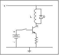
A circuit diagram also known as an electrical diagram, wiring diagram, elementary diagram, or electronic schematic is a simplified conventional pictorial representation of an electrical circuit. It shows the components of the circuit as simplified standard symbols, and the power and signal connections between the devices.

| Index: | * - A - B - C - D - E - F - G - H - I - J - K - L - M - N - O - P - Q - R - S - T - U - V - W - X - Y - Z 0–9 - a - b - c - d - e - f - g - h - i - j - k - l - m - n - o - p - q - r - s - t - u - v - w - x - y - z - ~ |
graphical representation of an electrical circuit (network)  | |||||
| Upload media | |||||
| Subclass of | |||||
|---|---|---|---|---|---|
| Depicts | electrical network | ||||
| Has part(s) | |||||
| |||||
Subcategories
This category has the following 33 subcategories, out of 33 total.
A
B
C
- Circuits for welding (2 F)
D
E
- Electro-Acoustic diagrams (16 F)
G
- Ground loops (15 F)
H
I
- Impedance matching circuits (20 F)
- Incorrect circuit diagrams (2 F)
L
- LCR circuits (151 F)
M
O
- Opto-isolator schematics (24 F)
P
R
- RL circuits (11 F)
T
- Tesla coil circuits (108 F)
- Thermocouple circuit diagrams (36 F)
- Thyristor equivalent circuits (10 F)
V
Pages in category "Circuit diagrams"
This category contains only the following page.
Media in category "Circuit diagrams"
The following 200 files are in this category, out of 976 total.
(previous page) (next page)-
IC Output OpenCollector 1.png 563 × 362; 3 KB
-
Ideal Buffers.png 608 × 487; 17 KB
-
Ideal Buffers.svg 608 × 487; 17 KB
-
Ignition system circuit diagram.svg 244 × 157; 12 KB
-
Ignitor.JPG 308 × 260; 9 KB
-
-
IMEQCCT.jpg 887 × 228; 19 KB
-
Impedance Diagram.jpg 804 × 556; 33 KB
-
ImpedanceMismatchCircuit.png 592 × 194; 8 KB
-
Impianto 1 FUNZIONALE.jpg 432 × 468; 13 KB
-
Inductance with 2 R.png 960 × 720; 23 KB
-
Inductance with 3 R differente.png 682 × 512; 8 KB
-
Inductance with 3 R.png 583 × 442; 11 KB
-
InductC.png 231 × 217; 1 KB
-
Circuitos elétricos adjacentes.jpg 585 × 266; 21 KB
-
Integrate-and-fire circuit diagram.png 500 × 400; 8 KB
-
INTERRUPTOR UNILATERAL DE SILICIO 3-6.jpg 944 × 466; 100 KB
-
Inverting summer classic.jpg 337 × 384; 27 KB
-
Isolationsmessung-Schaltung.svg 125 × 275; 14 KB
-
Itu-r 468-circuit.png 838 × 236; 11 KB
-
JerkCircuit01.png 922 × 571; 26 KB
-
KelvinBridge.gif 245 × 226; 7 KB
-
KHP lay 4.PNG 1,100 × 900; 46 KB
-
KHR 2.PNG 700 × 800; 25 KB
-
Klavesniceschema.png 1,144 × 710; 7 KB
-
Kmi.png 336 × 161; 3 KB
-
Knotenpotentialverfahren Bsp.svg 587 × 870; 55 KB
-
Kolmio+tähti.svg 328 × 128; 14 KB
-
Kompensation.png 466 × 483; 5 KB
-
Kopplinggschema.png 799 × 554; 30 KB
-
Kopplingsschema med lampa och motstånd.png 1,205 × 623; 59 KB
-
KramerGenerator.svg 600 × 410; 13 KB
-
Krets med 2 lampor.png 466 × 427; 24 KB
-
Krets med 2 motsånd.png 282 × 259; 17 KB
-
Krets med 3 motstånd.png 547 × 277; 36 KB
-
Krets med glödlampa och resistor.png 607 × 416; 41 KB
-
Krets med lampa och motstånd.png 567 × 341; 24 KB
-
Krets med Lampa.png 466 × 427; 26 KB
-
Krets med lampor.png 475 × 275; 26 KB
-
Krets med Lampor.png 466 × 427; 26 KB
-
Krets med motstånd och lampa.png 541 × 426; 35 KB
-
Krets med motsånd o lampa.png 480 × 401; 35 KB
-
Krets med resistans och 3 lampor.png 865 × 267; 25 KB
-
Krets schema.png 236 × 269; 17 KB
-
Krets v2.png 365 × 335; 18 KB
-
Krets, av Simon Viklund Te15B.png 674 × 489; 25 KB
-
Krets.png 365 × 297; 26 KB
-
Kretsschema.tiff 304 × 208; 14 KB
-
L ahel1.png 454 × 269; 4 KB
-
L ahel2.png 448 × 235; 3 KB
-
Lampes en parallèles.png 456 × 313; 10 KB
-
Launch Wave.svg 100 × 120; 61 KB
-
LC-circuit01.svg 245 × 331; 52 KB
-
LCD display.svg 746 × 472; 340 KB
-
Led circuit bb.jpg 2,964 × 2,625; 797 KB
-
LED strip.JPG 740 × 1,260; 84 KB
-
Legge di Ohm.png 658 × 510; 8 KB
-
Lihtne varaktormodulaatori skeem.jpg 1,024 × 802; 67 KB
-
Line Level Mixer.png 1,500 × 1,000; 296 KB
-
Lineafig1.jpg 763 × 408; 15 KB
-
LM386 combo schéma.jpg 485 × 416; 20 KB
-
LoudspeakerEquivalentCircuit.png 1,316 × 223; 40 KB
-
Low side current shunt.gif 564 × 473; 7 KB
-
Low side current shunt.svg 564 × 473; 29 KB
-
Low-pass Filter Example.png 283 × 127; 12 KB
-
Magic circuit.jpg 647 × 863; 104 KB
-
Manidips zenner diagram.jpg 3,752 × 1,812; 932 KB
-
Maximum Power Transfer Circuit.svg 275 × 175; 27 KB
-
Maxpowertheorem.png 256 × 150; 1 KB
-
Mechanical network symbols.svg 677 × 305; 46 KB
-
Medo5.gif 511 × 427; 12 KB
-
Meissner Patent.png 428 × 456; 9 KB
-
Memristor emulator.jpg 2,454 × 1,609; 234 KB
-
MFrey Bulb circuit.svg 1,250 × 450; 9 KB
-
Mfrey infrared remote control tester.svg 700 × 400; 27 KB
-
MFrey LED-Matrix PIC Schema.svg 1,500 × 880; 95 KB
-
MFrey RLC Zeigerdiagramm 001.svg 200 × 450; 10 KB
-
MFrey RLC Zeigerdiagramm 002.svg 200 × 450; 10 KB
-
MFrey RLC Zeigerdiagramm 003.svg 200 × 450; 10 KB
-
MFrey RLC Zeigerdiagramm 004.svg 225 × 450; 10 KB
-
MFrey RLC Zeigerdiagramm 005.svg 225 × 450; 9 KB
-
MFrey RLC Zeigerdiagramm 006.svg 225 × 450; 10 KB
-
MFrey ZDiode Current Source.svg 750 × 400; 7 KB
-
MFrey ZDiode Voltage Source.svg 1,200 × 500; 8 KB
-
MI-switch.PNG 191 × 132; 2 KB
-
MIDI IN OUT schematic.svg 694 × 229; 76 KB
-
MillerOpAmp.png 253 × 218; 1 KB
-
Mizar32 schematic V1.3.2.pdf 1,754 × 1,239, 3 pages; 299 KB
-
MK-diagram.png 519 × 434; 8 KB
-
MKO.jpg 752 × 348; 32 KB
-
MLS shiftregisters L4.png 640 × 129; 7 KB
-
Modèles parallèle et série d'un condensateur réel.png 385 × 132; 4 KB
-
Moltiplicatore1stadio.png 526 × 287; 8 KB
-
Montage déphaseur - bis.png 281 × 180; 8 KB
-
Montage déphaseur.png 273 × 181; 21 KB
-
Moteur m1 freinage recuperation.svg 270 × 356; 81 KB
-
Moteur m1 freinage rheostatique.svg 270 × 356; 78 KB
-
Moteur m1 traction.svg 270 × 356; 80 KB
-
Multiplicador de capacidad.JPG 471 × 311; 14 KB
-
Multiplieur électromécanique.PNG 599 × 382; 18 KB
-
Měření teploty multimetrem za použití LM35.jpg 720 × 328; 47 KB
-
Mạch lọc nguồn dùng tụ hóa và cuộn cảm.jpg 404 × 141; 21 KB
-
N+1 switch and diode.jpg 254 × 184; 9 KB
-
N+1 switch and diode.svg 254 × 184; 18 KB
-
Network implementing an artificial central pattern generator.png 4,668 × 2,167; 1.46 MB
-
Netzwerkanalyse baum.svg 1,100 × 300; 9 KB
-
Nfb block-diagram 65b 1000.jpg 1,000 × 809; 35 KB
-
-
Non-inv op-amp schmidt trigger 1000.jpg 1,000 × 758; 48 KB
-
Non-inv op-amp schmidt trigger volt diagram 1000.jpg 1,000 × 874; 55 KB
-
Nt1217.gif 1,000 × 968; 38 KB
-
Nullor circuit.svg 372 × 293; 28 KB
-
OB-Sprechstellenschaltung.png 567 × 416; 19 KB
-
OB-SprechstellePrinzipschaltung.png 567 × 416; 20 KB
-
Obrázek13aa.jpg 442 × 302; 15 KB
-
Obvod.svg 744 × 1,052; 25 KB
-
Ohm's Law with Current source.svg 200 × 150; 7 KB
-
Ohm's Law with Voltage source ru.svg 200 × 150; 2 KB
-
Ohm's Law with Voltage source TeX.svg 302 × 198; 8 KB
-
Ohm's Law with Voltage source.svg 200 × 150; 7 KB
-
Ohms law current source (white background).svg 512 × 512; 784 bytes
-
Ohms law current source.svg 512 × 512; 741 bytes
-
Ohms law diagram.jpg 1,170 × 501; 72 KB
-
Ohms law voltage source (white background).svg 285 × 209; 7 KB
-
Ohms law voltage source.svg 285 × 209; 7 KB
-
Ohmslawcurrentsource.png 165 × 106; 591 bytes
-
Ohmslawvoltagesource.png 143 × 118; 481 bytes
-
OP RCTiefpass.png 229 × 167; 2 KB
-
Op-amp circuits.jpg 3,084 × 1,864; 189 KB
-
Open circuit test.png 1,000 × 500; 21 KB
-
Opencircuit.PNG 306 × 174; 4 KB
-
Opt test.jpg 362 × 530; 23 KB
-
Ord2791W72k.jpg 1,198 × 598; 130 KB
-
Oscillations de relaxation d'une lampe au néon - bis.png 483 × 310; 11 KB
-
Oscillations de relaxation d'une lampe au néon.png 296 × 167; 3 KB
-
Oscillator circuit based on a LC realization of the Sierpinski triangle.png 2,146 × 2,408; 259 KB
-
Oscillatore a sfasamento.PNG 500 × 294; 15 KB
-
OscillatorSchematic.png 401 × 391; 23 KB
-
Panel 4lx.jpg 1,166 × 824; 79 KB
-
Parallel resistance diagram.jpg 1,053 × 849; 587 KB
-
Parallel-RC.png 329 × 148; 1 KB
-
Parallel-RL.png 329 × 148; 2 KB
-
ParallelCapacitorCircuit.PNG 1,285 × 465; 22 KB
-
ParalleleResonantieKring.gif 1,880 × 714; 22 KB
-
Parallellkopplad elkrets.jpg 627 × 310; 17 KB
-
Parasitic sensitive integrator.svg 406 × 181; 5 KB
-
Partitore di tensione con alimentatore.svg 218 × 162; 16 KB
-
Partitore di tensione.svg 80 × 400; 50 KB
-
Pb1+nsa.JPG 627 × 265; 28 KB
-
PC-PowerSupply-AC-in.svg 1,355 × 1,280; 102 KB
-
PC-PowerSupply-Principle-Circuit.svg 3,685 × 1,736; 103 KB
-
PCHB Dataless Buffer.svg 512 × 434; 16 KB
-
Pd mult.svg 479 × 145; 60 KB
-
PFD 3S F.jpg 742 × 548; 16 KB
-
PFD FF F.jpg 581 × 405; 7 KB
-
PFD FF JK.jpg 715 × 410; 12 KB
-
PFD GILBERT F.jpg 1,156 × 824; 34 KB
-
PFD TF F.jpg 992 × 810; 25 KB
-
PFD XOR F.jpg 611 × 369; 11 KB
-
Ph C.gif 156 × 302; 4 KB
-
Ph L.gif 161 × 302; 4 KB
-
Ph R.gif 153 × 302; 4 KB
-
Phantom power schema.svg 512 × 196; 9 KB
-
Phantom power.svg 1,843 × 1,063; 15 KB
-
Phase detector.svg 531 × 248; 35 KB
-
Phase Shift Oscillator v1.tif 1,302 × 852, 2 pages; 13.01 MB
-
Phase-convertor-circuit-diagram.png 1,214 × 529; 71 KB
-
Pi-Anpassstruktur.gif 684 × 211; 3 KB
-
Pinoutofic.png 1,359 × 546; 18 KB
-
Pirosensor.svg 2,202 × 595; 41 KB
-
Plasma actuator1.tiff 616 × 324; 40 KB
-
Plasma Actuator2.tiff 623 × 315; 41 KB
-
Poggschema.svg 385 × 195; 14 KB
-
Pojacavac.jpg 247 × 241; 9 KB
-
Pont diviseur de courant complexe - définition.png 507 × 232; 7 KB
-
-
-
Pont diviseur de courant en complexe fermé sur une charge.png 507 × 232; 8 KB
-
Pont diviseur de tension complexe - définition.png 533 × 233; 8 KB
-
-
Pont diviseur de tension en complexe fermé sur une charge.png 315 × 240; 7 KB
-
Ponte h.PNG 725 × 589; 87 KB
-
PotenCalibrate2.jpg 396 × 187; 31 KB
-
Potentiometer with load.png 396 × 187; 4 KB
-
Potentiometer with load.svg 474 × 177; 7 KB
-
Power detection.jpg 407 × 161; 29 KB
-
Power Sullpy Tester - 2-28-13.pdf 1,650 × 1,275; 17 KB
-
Power Supply Tester.pdf 1,650 × 1,275; 16 KB
-
Powerline-equivalent-circuit.gif 518 × 230; 3 KB
-
PP basic.PNG 300 × 200; 3 KB
-
Ppa schaltbild.svg 299 × 220; 120 KB
-
Practical Differentiator Circuit Diagram.jpg 1,920 × 1,079; 969 KB
-
Practical Differentiator Circuit Diagram.png 1,920 × 1,079; 8 KB
-
Practical Differentiator Circuit Diagram.svg 321 × 219; 9 KB
-
Preampcarica.pdf 612 × 481; 217 KB
-
Preampcarica.svg 392 × 308; 18 KB
-
Primera malla del circuito.png 658 × 624; 21 KB
-
Principe ESC.png 396 × 281; 20 KB
-
Prinzipschema Phasendetektor mit Flipflop.PNG 1,056 × 731; 28 KB
-
Problemalaplace1.jpg 499 × 495; 110 KB